
NetPlay Video Control4 driver setup (Virtual Video Walls):
In Control4, you are currently limited to defining no more than 4 custom button menus per room. Therefore we recommend using one of the following formats:
2x2 Virtual video wall
1x2 or 1x1 Virtual video wall + PIP
PIP only
Each room can use a different method as there are no inter-room dependencies.
Pre-setup:
Before setting up in Composer, make sure you have defined the VVW/Multidisplay formats and Video OSD/PIP formats you would like to use in the Virtual Matrix setup. For example, if using VVW 2x2 this is already the default format #1. For Video OSD, a small window in the lower right is default format #1.
All formats are defined by screen percentages. In VVWs, do not define overlapping video regions since this will create artifacts.
Composer setup:
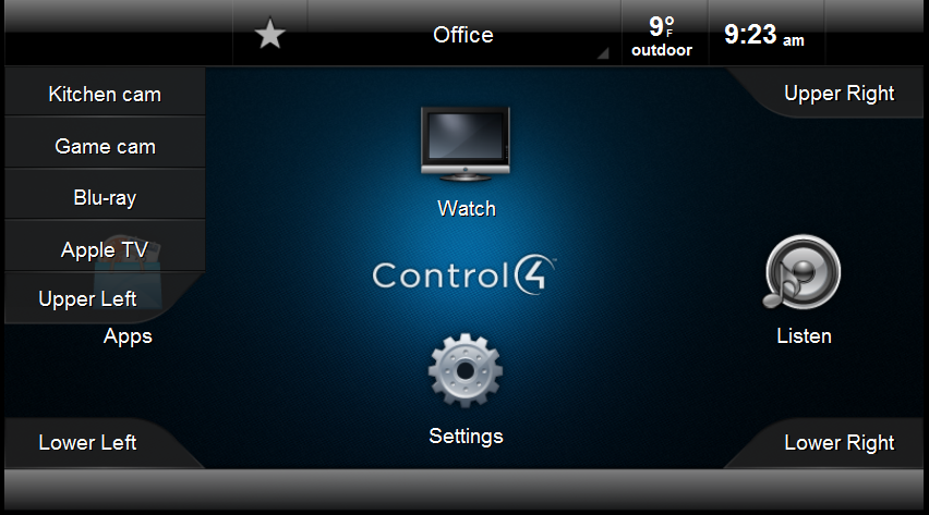
Control in Navigator is accomplished using custom buttons. This allows user control via any C4 device (not just the flash capable ones).
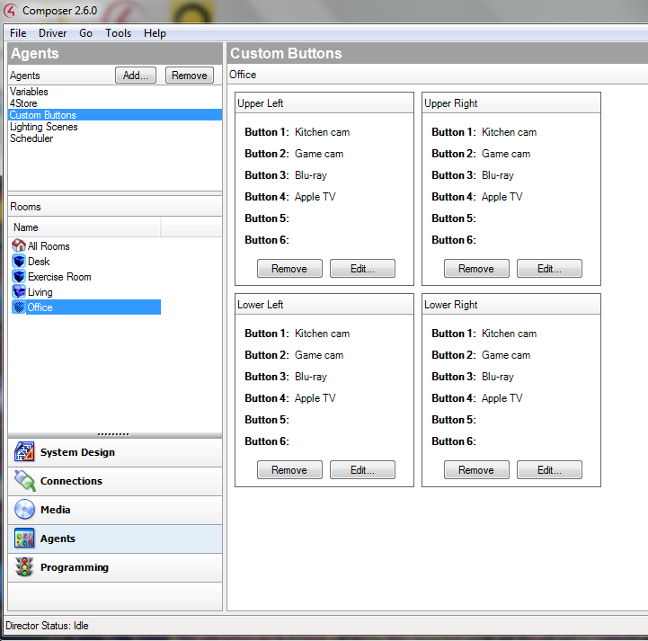
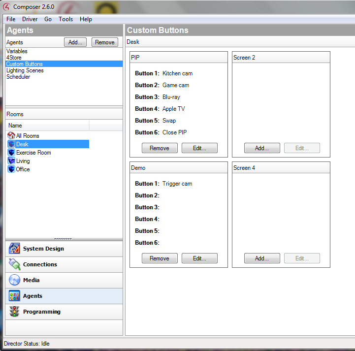
The first step is to define your custom buttons (agents tab). Since each menu is limited to 6 buttons, we recommend using different source options for each screen quadrant / menu.
Virtual Video Wall
PIP
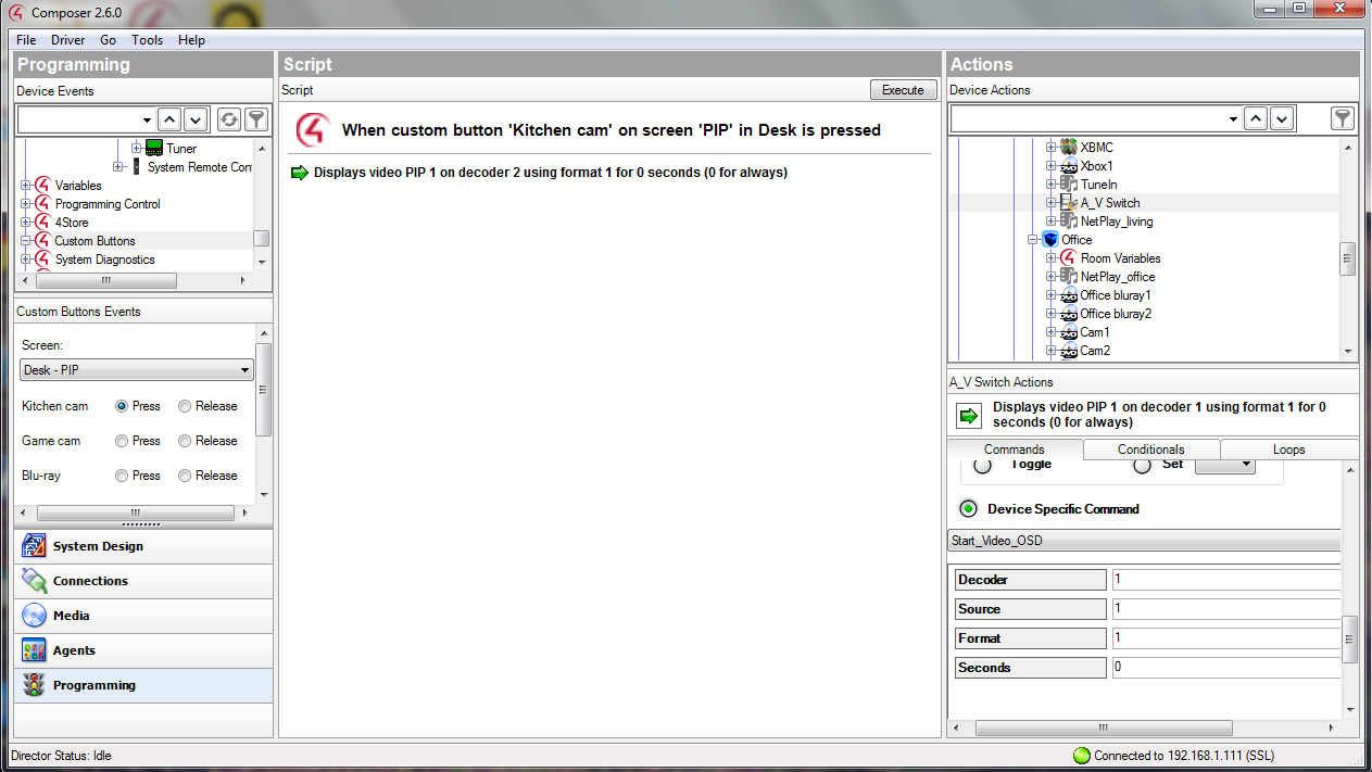
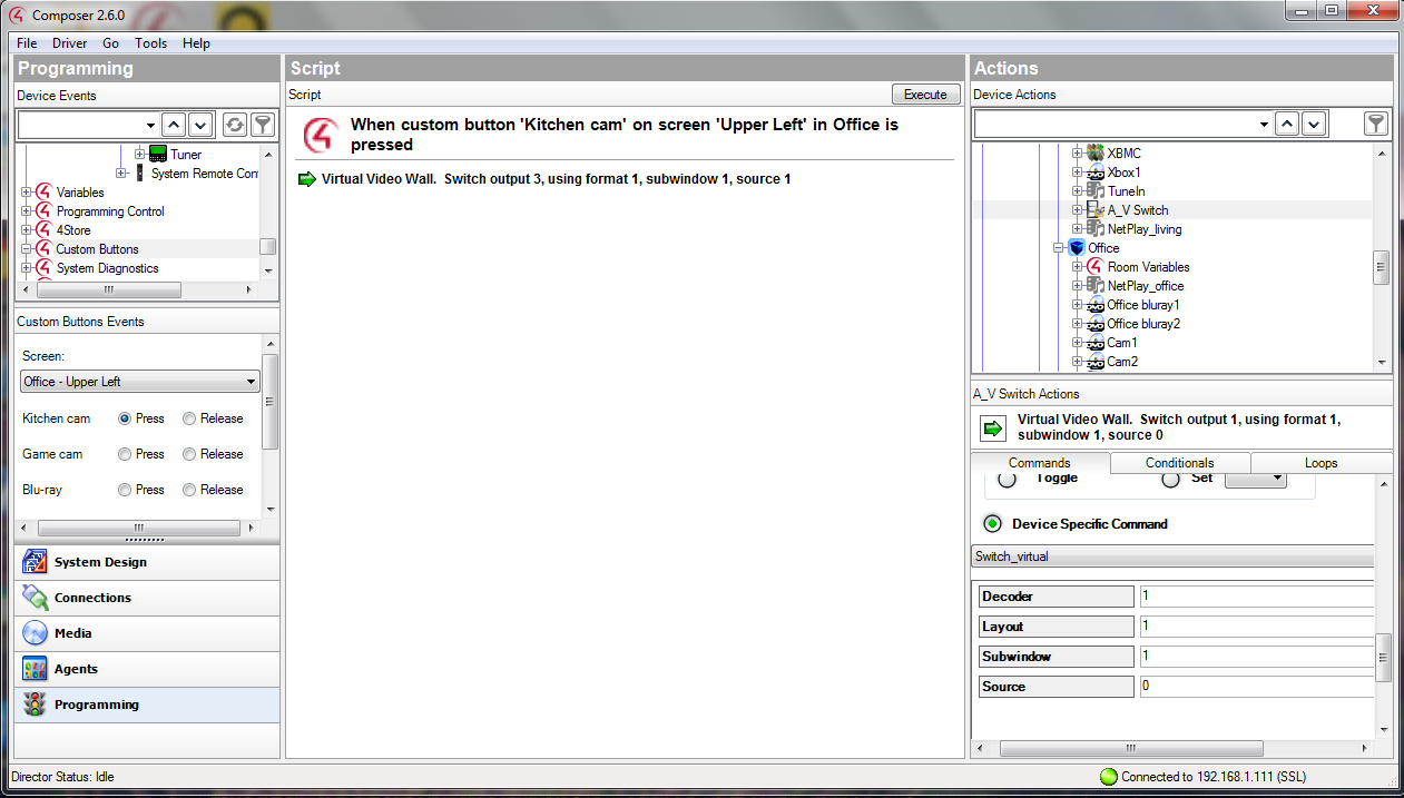
Next you use the programming tab to assign the NetPlay Video driver commands to each custom button.
For VVW:
Each button is assigned the "Switch_virtual" command from the NetPlay Video driver
The "Layout" field should be set to the Virtual matrix layout (2x2 is layout #1, etc)
"Decoder" field is the output # of this room (on the Virtual Matrix)
"Source" field is the input # of this source (on the Virtual Matrix)
"Subwindow" is the subwindow # this action will control
If the source for that button can be powered off, it is a good idea to add the source power on command here also
For PIP:
Each button is assigned the "Start_video_osd" command from the NetPlay Video driver
The "Layout" field should be set to the Virtual matrix layout (lower right is layout #1, etc)
"Decoder" field is the output # of this room (on the Virtual Matrix)
"Source" field is the input # of this source (on the Virtual Matrix)
"Seconds" should be set to 0 for the PIP to stay on until closed or source changes
Stop PIP would use the "Stop_video_osd" command
Swap PIP would use the "Swap_pip" command